Analysis and Treatment Methods of Air Trapped, Shrinkage, Sink Mark and Air Mark in Plastic Products
2022-05-29
Appearance defects such as trapped air, shrinkage cavities, sink marks and air streaks on injection molded products are usually the most important factors for customers to reject products. Although these quality defects are not the most common problems in injection molding, they can reduce the performance of products and are also urgent problems to be solved.
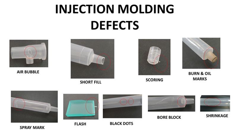
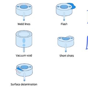
Cells are either gas trapped in the melt or vacuum holes formed in the product. What causes the bubbles in the product is very important for you to quickly find the source of the problem and decide what to do about it. A simple test can determine whether the cells are caused by trapped air or vacuum holes. Just heat the area of the product that contains air bubbles until it softens. If it is caused by trapped air, the air in it will expand when heated; if it is a vacuum hole, there is no air in it. Due to the force of the ambient atmospheric pressure on the walls of the softened product, the air bubbles will collapse. A heat gun is the best tool for heating these places, followed by a small lighter, and you can even use a torch if you're comfortable with your actions.
Air Trapped
Trapped air is the root cause of bubbles and air streaks. Air trapping can be related to flow front fusion or jetting, and can also result from equipment and processing issues such as missing vent inserts, poor venting, excessive decompression, and resin degradation. Gases may be generated by evaporation of moisture, volatiles in resins, material degradation, and may be trapped in ribs, threads, or protruding structures on the base that are not vented. The pattern of melt flow is one of the main causes of bubbles. The process engineer should examine the flow pattern of the product by means of a short shot to determine if the flow front is producing a surrounding flow. It is worth noting that if there is a racetrack effect or jetting phenomenon, it is easy to trap the gas inside the melt.
Observe the flow behavior at the backflow or blind tendon with trapped air. Inspect the product and determine if the rib or the product's support structure has been filled before the product is completely filled. If it is a problem with the flow pattern, a series of short shots are used to complete different degrees of short shots (10% to 95% of the product volume) by changing the switching position or the injection volume. In this way, the location and origin of bubbles can be found. This test requires speed control in the first stage (of the filling process), and if the pressure and speed of the first stage are reduced, it will be difficult to complete the entire test.
Other factors that can cause bubbles and streaks from trapped gas include insufficient venting, flow pattern design of the melt, and tumbling of gas onto the product surface during filling or holding. Problems with melt flow patterns may mean that gate locations need to be changed to avoid racetrack effects, trap air, or to promote fill balance.
Equipment can also be the cause of air bubbles. If you are using a hot runner system, due to the Venturi effect, it can suck air from the middle of the plate into the hot runner, thereby entering the melt to form bubbles. In order to confirm this problem, the mold needs to be disassembled, and the blue dye needs to be placed near the hot nozzle. Be careful not to place it on the flow path. If the blue dye is present on the product, then you can identify the source of the problem.
It is also possible to determine whether the bubbles originate from the barrel or the screw by checking the standard air injection time (the state of the plastic melt). General-purpose screws with an aspect ratio of 18:1 or less can be the culprit for air bubbles or streaks. One solution is to increase the back pressure to a level of 1000-1500 psi pressure. Another solution is to vacuum the mold before injection, so that the gas can be evacuated. Moisture adhering to the molding system is also one of the causes of this problem.
Die venting is also a big problem, and trapped air can be eliminated by using proper venting methods or utilizing vented steel. Check the number of vent inserts and the depth of the vent grooves. The exhaust state can be checked with pressure sensitive paper. Clean the parting surfaces and core side vent inserts to reduce the chance of trapped air.
Shrinkage and Sink Marks
Shrinkage cavities are generated during the cooling process, and usually appear where the product is thicker, and the cooling rates of the core and skin layers in this area of the product are significantly different. Sink marks are dents on the surface of the product, and the product cannot replicate the condition of the mold surface in that area.
Shrinkage cavities and sink marks mean the existence of residual stress and are also a warning signal that the ideal product cannot be produced. Insufficient replenishment is one of the main reasons for shrinkage cavities and sink marks, so it is particularly necessary to punch more plastic into the cavity by holding pressure. The craftsman must ensure a consistent material pad during the molding, so as to ensure that the screw head will not be damaged. You may use high packing pressure and long packing time during the packing phase. In order to solve shrinkage cavities and sink marks, the injection rate can be reduced, the gas back pressure can be used, and the back pressure can be increased. It can ensure that the gate is continuously unblocked to obtain a longer gate freezing time, so that the pressure holding in the second stage will be more sufficient. Technologists can also try lowering the melt temperature.
From a processing point of view, the diameter of the runner and gate can be increased. The first thing to do is to identify where the contraction is taking place. Is it near the gate or at the end of the stream. If near the gate, check the gate freezing time. If at the end of the product stream, the injection speed can be increased to reduce the viscosity to facilitate transfer of holding pressure.
Another way to eliminate shrinkage cavities or sink marks is to reduce the nominal wall thickness. Thicker areas in a plastic product are not necessarily where the strength is stronger. If there are strength requirements in this place, you can redesign this place and design some reinforcing ribs at the same time. This not only saves material but also shortens the molding cycle. If available, the mold designer can cut holes in the thick walls. Of course, the first consideration in the mold is to place the gate in the thick wall area, which allows more melt (before the gate freezes) to enter the cavity. The craftsman can also greatly increase the mold temperature and/or eject the product earlier so that the outer wall of the product will sag (as the core shrinks) during natural cooling to avoid shrinkage cavities.
For sink marks, try cooling the product in water or between aluminum sheets instead of air. In this way, once ejected, the core material in the thicker areas of the product will reheat or melt its outer surface and allow it to sink with the core. Although this method may result in the creation of vacuum holes. You may be able to reduce the risk of vacuum holes by not cooling the surface of the product and keeping it warm by placing it on wood or insulating foam. But using this method may produce sink marks.
Air Streak
Air streak is a film formed by air bubbles on the surface of the product, which can also affect the appearance of the product. Bubbles can be formed by gas tumbling onto the product surface during filling or pressure holding, or caused by trapped gas issues (inadequate venting, melt flow pattern/screw L/D ratio), and the solution is the same. However, air streaks may also occur due to molding process issues, resin degradation, or compound additive issues. Delamination is a very serious cosmetic defect.
Excessive injection rates can create air streaks, which can form a thin, highly oriented skin layer on the surface of the molded product. Sometimes the tape is attached to the product and the thin layer can be peeled off when the product is lifted. Therefore, a lower injection rate can be used when injection molding. If the mold temperature near the gate is too high, air streaks can also occur, so if feasible, the cooling at the gate can be strengthened. If the pressure drop on the screw is too high, it may push air to the nozzle creating trapped air. Such air pockets enter the melt through nozzles connected to the main flow channel. If it is a hot runner system, the trapped gas moves through the hot runner system and creates bubbles during injection. In the case of a cold runner system, the gas is pushed to the front of the flow front and can be removed.
Gases can also be produced by the decomposition of resins or additives, so when trying new batches and/or materials that have never been used, it is best to check that the melt temperature is within the range recommended by the material supplier. Technologists should also minimize the residence time of the melt, such as using a barrel with a suitable injection volume.
Please ensure that the length-diameter ratio (L/D) of the plasticizing screw is above 20:1. If the frequency of air streaks has been reduced by longer molding cycles and higher back pressure, then it may be an issue with the screw design.
Recent Posts